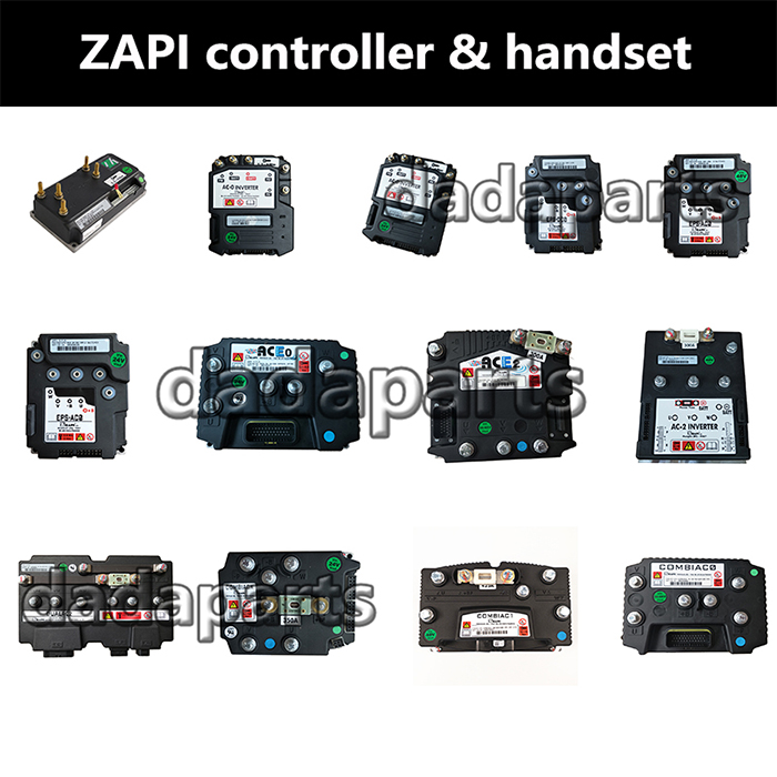
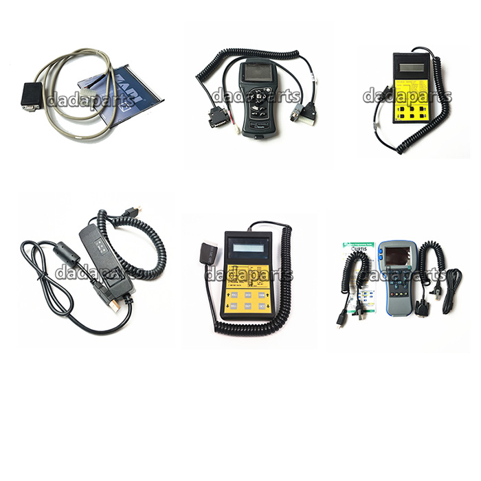
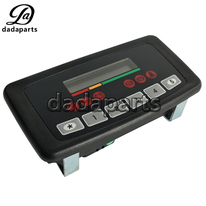
ZAPI smart display FC9050 FC9026 FC9028 FC9036 for electric forklift truck
| Product name | ZAPI SMART DISPLAY |
| DDP# | DDPYBFTY90Q14 |
| Voltage | 48V/80V |
| Size | Standard size |
| Color | Black |
| Size | Standard size |
| Used for | three/four-wheel Electric forklift |
| Product name | ZAPI SMART DISPLAY |
| DDP# | DDPYBFTY90Q14 |
| Voltage | 48V/80V |
| Size | Standard size |
| Color | Black |
| Size | Standard size |
| Used for | three/four-wheel Electric forklift |
| Product name | ZAPI SMART DISPLAY |
| DDP# | DDPYBFTY90Q14 |
| Voltage | 48V/80V |
| Size | Standard size |
| Color | Black |
| Size | Standard size |
| Used for | three/four-wheel Electric forklift |


If you need the zapi smart display user manual ,please contact us.
Tester menu
Following parameters can be measured in real time in the TESTER menu:
BRUSHES ON/OFF Level of DI0 input – Motor brushes (A5)
ON = Input active
OFF = Input not active
PUMP MOT TEMP ON/OFF Level of DI1 input – Pump motor temperature (A6)
ON = Input active
OFF = Input not active
HYD OIL LEVEL ON/OFF Level of DI12 input – Hydraulic oil level (A9)
ON = Input active
OFF = Input not active
BRAKE OIL ON/OFF Level of AI input – Brake fluid level (A10)
ON = Input active
OFF = Input not active
DIGITAL INPUT #1 ON/OFF Level of DI3 input – Spare input (A11)
ON = Input active
OFF = Input not active
SEAT SWITCH ON/OFF Level of DI5 input – Seat input (A13)
ON = Input active
OFF = Input not active
SEATBELT SWITCH ON/OFF Level of DI6 input – Seatbelt input (A14)
ON = Input active
OFF = Input not active
HANDBRAKE ON/OFF Level of DI4 input – Handbrake input (A12)
ON = Input active
OFF = Input not active
STATUS #0 ON/OFF 0: Status of ( * ) keyboard button:
ON = input active, button pushed
OFF = input not active, button released
STATUS #1 ON/OFF Status of ( 1 ) keyboard button:
ON = input active, button pushed
OFF = input not active, button released
STATUS #2 ON/OFF Status of ( 2 ) keyboard button:
ON = input active, button pushed
OFF = input not active, button released
STATUS #3 ON/OFF Status of ( 3 ) keyboard button:
ON = input active, button pushedOFF =
input not active, button released
STATUS #4 ON/OFF Status of ( 4 ) keyboard button:
ON = input active, button pushed
OFF = input not active, button released
STATUS #5 ON/OFF Status of ( 5 ) keyboard button:
ON = input active, button pushed
OFF = input not active, button released
DISPLAY TYPE 0/1 Information about display type
0 = standard
1 = premium
Smart Display alarms
“EEPROM KO”
Fault in the area of memory where the adjustment parameters are stored. This
Alarm does not inhibit machine operation but operation goes on with default
values; if fault is still present when the Key Switch is re-cycled, replace the Smart
Display. If the fault disappears, the previously stored Parameters will have been
replaced by the default parameters.
“CANBUS KO “
Smart Display does not receive messages from canbus line.
Trouble shooting:
– If this fault code is displayed together with other alarm messages, the fault is
probably to be looked for in the Smart Display can interface, since the
Display seems to be unable to receive any can message. So it is suggested
to check Smart Display canbus wiring and connection.
– Otherwise, the fault is in the can interface of other modules present on
canbus net.
“SERVICE REQUIRED”
The maintenance time is elapsed, service intervention required.
“COIL SHORTED”
Loads connected to one of the power output (A19 and A20) are shorted; thus
providing a overcurrent on the related drivers.
Trouble shooting:
– Check the loads connected, if they are burnt or shorted.
– Check the related wiring.
– If the alarm is present even with open connections (no loads connected), the
Smart Display high current protection circuit is damaged, replace the Smart
Display.
“HYDRAULIC OIL”
Hydraulic oil level input is active at start-up.
Trouble shooting:
Check if the related digital input on the display (A9) is active (see TESTER
menu).
Check also which active level (+VB or GND) is selected for this input (SET
OPTIONS menu).
– If this input is active, check the related switch status, the wiring and oil level.
– If the input is not active the failure is probably in the Smart Display input
circuit.
“PUMP MOTOR TEMPERATURE”
Hoist motor temperature device signal an hot temperature in the motor windings.
Trouble shooting:
Check if the related digital input on the display (A6) is active (see TESTER
menu).
Check also which active level (+VB or GND) is selected for this input (SET
OPTIONS menu).
– If the fault message is present when the input is active check hoist motor
temperature, wiring, and motor temperature sensor, it is probably failed
opened.
– If, on the contrary, the input is not active, probably Smart Display input circuit
is damaged.
“BRUSHES”
Hoist motor brush wear sensor signal brush wearing.
Trouble shooting:
Check if the related digital input on the display (A5) is active (see TESTER menu).
Check also which active level (+VB or GND) is selected for this input (SET OPTIONS menu).
– If the fault message is present when the input is active check brush wearing,
wiring, and brush wear sensor.
– If, on the contrary, the input is not active, probably Smart Display input circuit is damaged.