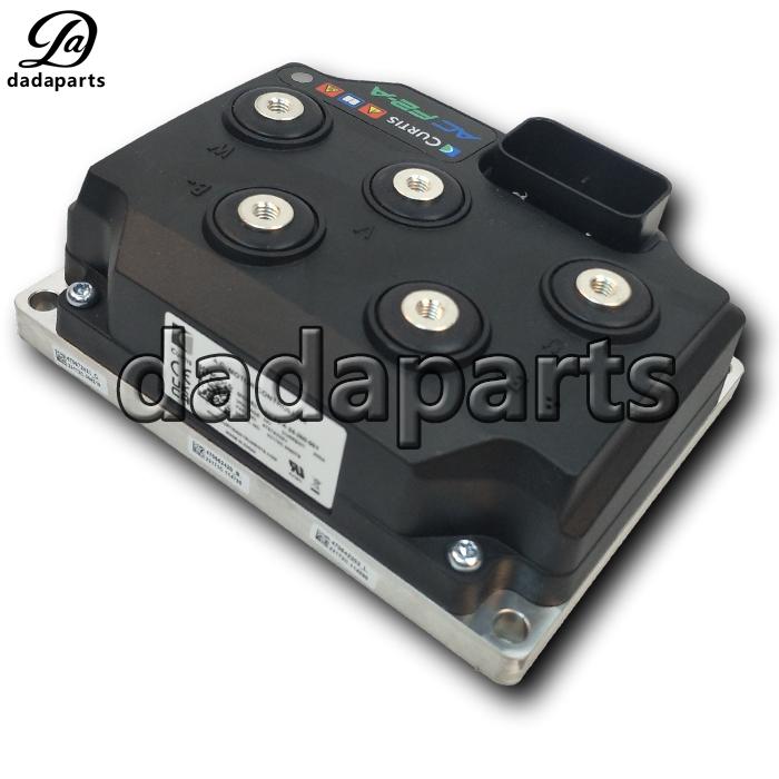
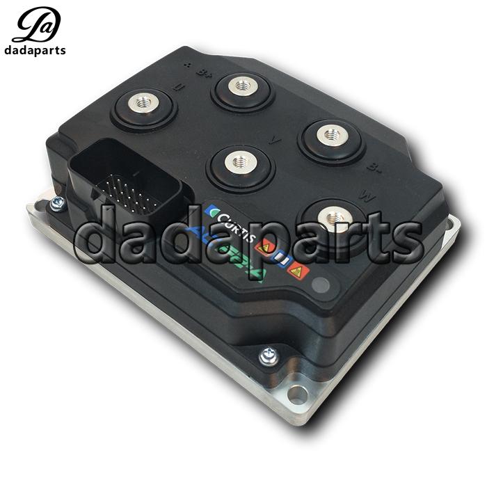
Curtis controller AC F2-A 24-200-001 24V 200A
| Product name | Curtis controller |
| Part number | 470762201 |
| Model | AC F2-A 24-200-001 |
| Voltage | 24V |
| Current | 200A |
| Used for | electric stacker / Pallet JACK |
| Product name | Curtis controller |
| Part number | 470762201 |
| Model | AC F2-A 24-200-001 |
| Voltage | 24V |
| Current | 200A |
| Used for | electric stacker / Pallet JACK |


Low Power Wiring Guidelines
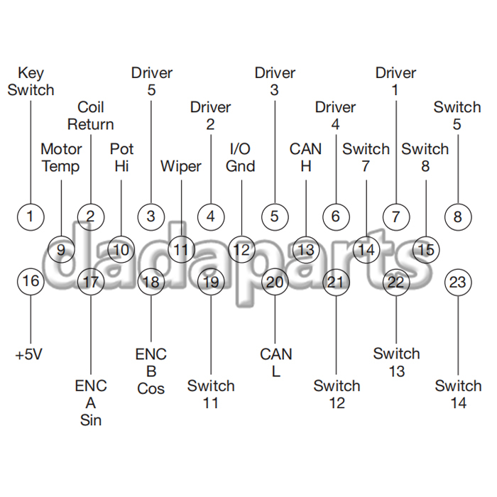
The generic 23-pin I/O assignments illustrated below are described in Table 2. This is the wiring
diagram configuration shown in Figure 5. Most inputs and outputs (I/O) can be configured through
parameter settings to operate as a digital switch input, an analog input, or in one case a 12 V power
supply. The alternative uses are listed in Table 2 and further details in the type Tables 4–13.

Rotor Position feedback (Pins 12, 16, 17, 18)
All four wires (+5 V, Feedback A, Feedback B, and I/O ground) should be bundled together as they
run between the motor and controller logic connector. These can often be run with the rest of the low
current wiring harness. The encoder cables should not be run near the motor cables. In applications
where this is necessary, shielded cable should be used with the ground shield connected to the I/O
ground (pin 12) at only the controller side. In extreme applications, common mode filters (e.g. ferrite
beads) could be used.

CANbus (Pins 13 and 20)
It is recommended that the CAN wires be run as a twisted pair. However, many successful applications
at 250 kbit/s are run without twisting, simply using two lines bundled in with the rest of the low
current wiring. The CANbus wiring should be kept away from the high current cables and cross
them at right angles when necessary.
All other low power wiring
The remaining low power wiring should be run according to standard practices. When designing
the vehicle’s wiring and routing, keep the input lines such as throttle, temperature, and the above
mentioned motor feedback signals separate from controller’s output lines such as the coil driver
outputs. Avoid routing the low-power wiring parallel to the high power (and current) battery and
motor cables.
Protected voltages
The low-power pins’ protected voltage ratings listed in Table 3 are absolute and therefore are not
intended for normal operation. To prevent damage to the controller, do not connect (short circuit)
the Coil Return (pin 2) to battery negative. Further, do not connect (short circuit) the I/O Ground
(pin 12) to battery positive.