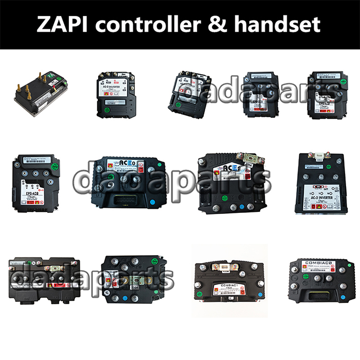
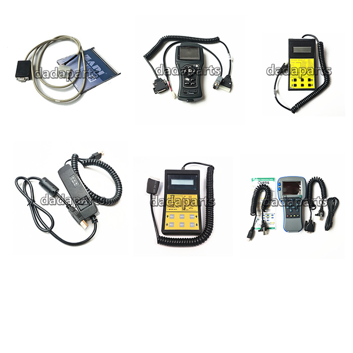
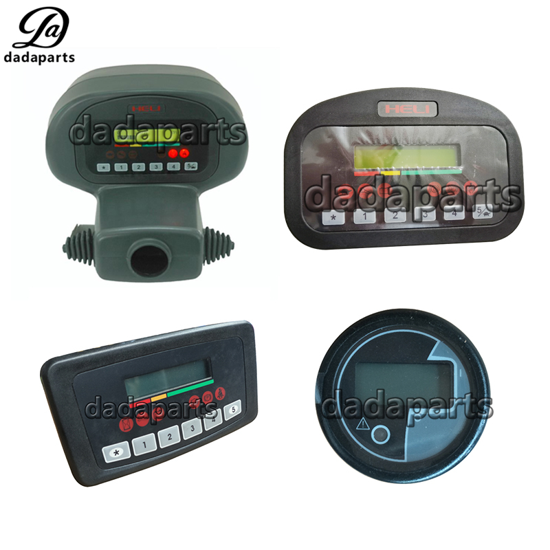
A6H12-40051 A71Y2-40701Q ZAPI smart display 48V80V A6V92-40061
| Product name | ZAPI SMART DISPLAY |
| DDP# | DDPYBFHL90Q15 |
| Voltage | 48V/80V |
| Size | Standard size |
| Color | Black |
| Size | Standard size |
| Used for | three/four-wheel Electric forklift |
| Product name | ZAPI SMART DISPLAY |
| DDP# | DDPYBFHL90Q15 |
| Voltage | 48V/80V |
| Size | Standard size |
| Color | Black |
| Size | Standard size |
| Used for | three/four-wheel Electric forklift |
| Product name | ZAPI SMART DISPLAY |
| DDP# | DDPYBFHL90Q15 |
| Voltage | 48V/80V |
| Size | Standard size |
| Color | Black |
| Size | Standard size |
| Used for | three/four-wheel Electric forklift |


If you need the zapi smart display user manual ,please contract us.
Connector description
PIN FUCTION DESCRIPTION
A1
+key Smart Display positive power supply.
A2 CMM Positive supply of digital input devices.
A3 -BATT Smart Display negative supply.
A4 -BATT Smart Display negative supply.
A5 DI 0 Digital Input, range -BATT/+BATT; Zapi function:
MOTOR BRUSHES, active level setted by console.
A6 DI 1 Digital Input, range -BATT/+BATT; Zapi function:
HOIST MOTOR TEMPERATURE, active level setted
by console.
A7 CAN_L Can low signal.
A8 CANPOS Positive of isolated canbus interface; used in case of
optoisolated CANBUS.
A9 DI 2 Digital Input, range -BATT/+BATT; Zapi function:
HYDRAULIC OIL LEVEL, active level setted by
console.
A10 AI Analog Input, range -BATT/+12V; internal pull-up to
+12V provided; Zapi function: BRAKE FLUID LEVEL
A11 DI 3 Digital Input, range -BATT/+BATT; Zapi function: spare
input, active level setted by console.
A12 DI 4 Digital Input, range -BATT/+BATT; Zapi function:
HAND BRAKE, active level setted by console.
Handbrake LED is lighted when this input become
active or when active handbrake information is present
on CANBUS line.
A13 DI 5 Digital Input, range -BATT/+BATT; Zapi function:
SEAT, active level setted by console. Seat LED is
lighted when this input become not active or when
missing seat information is present on CANBUS line.
A14 DI 6 Digital Input, range -BATT/+BATT; Zapi function:
SEATBELT, active level setted by console.
A15 CAN_T CAN termination; connect to CAN-H (A22) to insert can
termination resistance.
A16 OUT LOW CURR Low current, open collector output, driving to -BATT;
max current : 100 mA.
A17 +BATT-IN Positive supply input; this input has to be connected to
+BATT, taking the signal before key switch. A17
supplies the Smart Display when key is OFF (service time) and supplies the built-in heater (frozen cell
version).
A18 -BATT Smart Display negative supply.
A19 OUT 1 Power open collector output, driving to -BATT; max
current 2,5A. Zapi function: output activated in case of
backward request read from canbus line. Function
present only if option OUTPUTS ENABLE is setted ON
(see chapter 4.4).
A20 OUT 2 Power open collector output, driving to -BATT; max
current 2,5A. Zapi function: output activated in case of
alarm read from canbus line. Function present only if
option OUTPUTS ENABLE is setted ON (see chapter
4.4).
A21 +BATT-OUT Positive supply for loads / switches, max current 3A.
A22 CAN_H Can signal high.
A23 CAN NEG Negative of CAN circuit, to be used in case of
optoisolated CANBUS.
B1 PCLRXD Positive serial reception.
B2 NCLRXD Negative serial reception.
B3 PCLTXD Positive serial transmission.
B4 NCLTXD Negative serial transmission.
B5 GND Negative console power supply.
B6 +12 Positive console power supply.
B7 FLASH Flash memory programming via serial link – Zapi
standard tool.
B8 FLASH Flash memory programming via serial link – Zapi
standard tool.

Alarms visualisation
When an alarm condition occurs, Smart Display gives the information showing
the alarm code in the first row and the module number in the second row.
For example, the information:
A L A R M 6 0
O N N O D E 5
means that the alarm 60 occurred in the module N.5 (pump).
Here is shown the table with the alarm codes and the respective meaning.
The meaning of alarms with a code higher than 99 can change depending on the
purpose of the application.
00 NONE
01 CHOPPER RUNNING
02 NO COMMUNICATION
03 UNKNOWN CHOPPER
04 CONSOLE EEPROM
05 SERIAL ERROR #2
06 SERIAL ERROR #1
07 CHOPPER NOT CONF
08 WATCHDOG
09 FIELD FF FAILURE
10 EEPROM DATA KO
11 EEPROM PAR. KO
12 EEPROM CONF. KO
13 EEPROM KO
14 EEPROM OFFLINE
15 LOGIC FAILURE #5
16 LOGIC FAILURE #4
17 LOGIC FAILURE #3
18 LOGIC FAILURE #2
19 LOGIC FAILURE #1
20 FORW VMN LOW
21 FORW VMN HIGH
22 BACK VMN LOW
23 BACK VMN HIGH
24 LEFT VMN LOW
25 LEFT VMN HIGH
26 RIGHT VMN LOW
27 RIGHT VMN HIGH
28 PUMP VMN LOW
29 PUMP VMN HIGH
30 VMN LOW
31 VMN HIGH
32 VMN NOT OK
33 NO FULL COND.
34 RGT NO FULL COND
35 LFT NO FULL COND
36 PU NO FULL COND
37 CONTACTOR CLOSED
38 CONTACTOR OPEN
39 BRAKE CON CLOSED
40 BRAKE CONT. OPEN
41 DIR CONT. CLOSED
42 DIR CONT. OPEN
43 RIGHT CON CLOSED
44 RIGHT CONT. OPEN
45 LEFT CONT CLOSED
46 LEFT CONT. OPEN
47 MAIN CONT CLOSED
48 MAIN CONT. OPEN
49 I=0 EVER
50 LEFT I=0 EVER
51 RIGHT I=0 EVER
52 PUMP I=0 EVER
53 STBY I HIGH
54 LEFT STBY I HIGH
55 RGT STBY I HIGH
56 PUMP STBY I HIGH
57 HIGH FIELD CUR.
58 NO FIELD CUR.
59 HIGH BRAKING I
60 CAPACITOR CHARGE
61 HIGH TEMPERATURE
62 TH. PROTECTION
63 THERMIC LEVEL #2
64 PUMP TEMPERATURE
65 MOTOR TEMPERAT.
66 BATTERY LOW
67 BATTERY LEVEL #2
68 BATTERY LEVEL #1
69 CURRENT SENS. KO
70 HIGH CURRENT
71 POWER FAILURE #3
72 POWER FAILURE #2
73 POWER FAILURE #1
74 DRIVER SHORTED
75 CONTACTOR DRIVER
76 COIL SHORTED
77 COIL INTERRUPTED
78 VACC NOT OK
79 INCORRECT START
80 FORW + BACK
81 BAD STEER 0-SET
82 ENCODER ERROR
83 BAD ENCODER SIGN
84 STEER SENSOR KO
85 STEER HAZARD
86 PEDAL WIRE KO
87 PEDAL FAILURE
88 TRACTION BRUSHES
89 PUMP BRUSHES
90 DRIVER 1 KO
91 DRIVER 2 KO
92 DRIVER 1 SIC. KO
93 DRIVER 2 SIC. KO
94 INPUT ERROR #6
95 INPUT ERROR #5
96 INVERTION
97 POSITION HANDLE
98 INPUT ERROR #2
99 INPUT ERROR #1
If you need the zapi smart display user manual ,please contract us.